I remember playing Spyro: Reignited Trilogy for the first time, and just being hit with an immense level of nostalgia - everything felt familiar, like going back to your childhood home, but it felt fresh, with a new coat of paint and few renovations here and there.
One thing that stood out to me was portals Spyro uses to travel between the worlds. They received a graphical upgrade compared to the original PlayStation 1 games, that made them so much more interesting to look at - I could just watch them all day with the calm music in the background.
Reference Breakdown#
When re-creating effects from games, I like to start by breaking down my goal into more manageable sections. Looking at the reference video, we can identify a few layers of effects we’ll need to tackle to achieve the same effect:
- Background: Background appears to have depth, as depending on the viewing angle we can see different parts of it.
- Blur: Background seems to have some blur applied to it, as it isn’t super sharp when looking through the portal.
- Distortion: Background is constantly being distorted by an animated effect.
- Edge Glow: There is a soft glow around the edge of the ‘inner’ part of the portal.
Now that we know what we need to do, let’s tackle each layer one at a time.
Scene Setup#
Before starting on the shader, I set up a simple testing scene - I have a portal model which I grabbed from Sketchfab, and I removed the chains, torches, leaves, and the inner part as we’ll be handling that part ourselves.
I created a simple flat plane to fill the middle making sure it slightly overlaps the actual bricks of the portal so we don’t get any gaps.
Next, we want to create a new sorting layer called “PortalWorld” - this layer will contain the worlds that we will see through the portal, allowing us to disable them from being rendered on the main camera.
Finally, we want to create a second camera called “Portal Camera”, and parent it to the main camera (remember to reset the portal camera transform). In my case, the main camera is parented to the player, so when I navigate the level both cameras will follow.
In the portal camera, we want to tweak the Output Texture field (under Output Settings) and assign a new render texture (Create > Rendering > Render Texture). We will only need one render texture for all portals.

Project, and source code with assets available in GitHub repository below.
If everything has been set up correctly, when we run Unity we should see the render texture update in inspector.

Background#
The background can be split into two sections: the background shown on the portal inner part, and the world rendered to the render texture. We will be using the render texture as the main texture in our shader to create the background, and we will be using creating a world that is seen inside of the portal on a separate layer.
World “Inside” Portal#
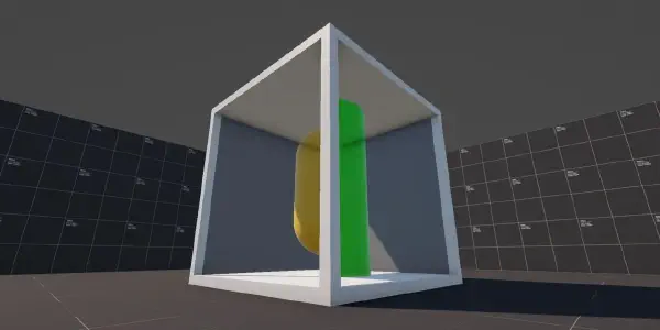
I started by creating a sphere and a unlit URP material, and I assigned the newly created material to our sphere. We need to make sure to set the Render Face option to Back as we want to see the inside of the sphere (otherwise it would appear invisible).
Next I made the sphere as the child of the portal inner, and I moved it slightly off-center behind the portal (in the direction players would be looking at it).

For the background image, I went into the Fracture Hills level and I grabbed an ultra-wide screenshot of the world. Rather than blurring the image in real-time in the shader, I have applied a Gaussian blur to the background using image-editing software. I then applied the texture to our sphere material.
We could apply the blur in-shader, but I don’t think the quality difference is noticeable enough to justify it - additionally, when we have multiple portals in the world, that will be quite few calculations for something we can have baked-in.
Shader Background#
Now that we have our world sphere, we can start working on the portal inner shader - I started off by creating a URP unlit shader, and cleaning it up and only leaving things we actually need.
Shader Code
Shader "DP/PortalInner"
{
    Properties
    {
        [MainTexture] _BaseMap("Base Map", 2D) = "white" {}
    }

    SubShader
    {
        Tags {
            "RenderType" = "Opaque"
            "RenderPipeline" = "UniversalPipeline"
        }

        Pass
        {
            HLSLPROGRAM
            #pragma vertex vert
            #pragma fragment frag

            #include "Packages/com.unity.render-pipelines.universal/ShaderLibrary/Core.hlsl"

            struct Attributes
            {
                float4 positionOS : POSITION;
                float2 uv : TEXCOORD0;
            };

            struct Varyings
            {
                float4 positionHCS : SV_POSITION;
                float2 uv : TEXCOORD0;
            };

            TEXTURE2D(_BaseMap);
            SAMPLER(sampler_BaseMap);

            CBUFFER_START(UnityPerMaterial)
                float4 _BaseMap_ST;
            CBUFFER_END

            Varyings vert(Attributes IN)
            {
                Varyings OUT;

                OUT.positionHCS = TransformObjectToHClip(
                    IN.positionOS.xyz
                );

                OUT.uv = TRANSFORM_TEX(
                    IN.uv,
                    _BaseMap
                );

                return OUT;
            }

            half4 frag(Varyings IN) : SV_Target
            {
                half4 color = SAMPLE_TEXTURE2D(
                    _BaseMap,
                    sampler_BaseMap,
                    IN.uv
                );

                return color;
            }
            ENDHLSL
        }
    }
}
If you create a material, which uses our new shader, assign it to the portal inner mesh and set the render texture as main texture you will notice something strange when playing the game - the background is moving with our player!
UV Mapping#
This behavior is expected - although not correct for our case. The reason we’re seeing this is because the second camera is moving with the player, and what we are displaying is the output from that camera; so as we move closer to the portal, the background becomes larger and as we move away, the background becomes smaller.
We can tackle this problem by applying some clever math. This was a new area to me, but thankfully Sebastian Lague has made an excellent tutorial on portals, and the texture mapping is also covered there.
“This [the texture mapping] is like taking the view texture, and just cutting out the region that overlaps with the screen of the portal.”
Sebastian explains this approach really well in the video, with visual examples, so I highly recommend giving at least the timestamped part a watch.
Instead of using the object UVs, we will use the screen position of the mesh vertices as our UVs; this will result in the background staying in place.
In order to achieve this effect, we will need to provide the screen position to the fragment shader; luckily Unity has a built-in function that can handle this for us.
struct Varyings
{
    // ...

    float4 screenPos : TEXCOORD1;
}

Varyings vert(Attributes IN)
{
    // ...

    OUT.screenPos = ComputeScreenPos(OUT.positionHCS);

    return OUT;
}
Now we can calculate our screen space UVs by dividing the x and y components by w - this is something that Sebastian also covers in the video. This is required in order to correctly apply perspective distortion (the further the object is from the camera, the higher the value) to our image.
half4 frag(Varyings IN) : SV_Target
{
    float2 screenSpaceUV = IN.screenPos.xy / IN.screenPos.w;

    half4 color = SAMPLE_TEXTURE2D(
        _BaseMap,
        sampler_BaseMap,
        screenSpaceUV
    );

    return color;
}Distortion#
Now that we have our background rendering correctly, we can tackle something a little easier. As previously noted, the background in Spyro’s version of the portal has a small distortion that is constantly animating.
Sampling Noise#
We can achieve this easily by sampling a noise texture and modifying the UVs we have just calculated by adding the noise on top of the UVs. Let’s add a new property to our shader called DistortMap, calculate the UVs for it in vertex shader, and sample it using the new UVs in fragment shader.
// Inside Properties object
_DistortMap("Distortion Texture", 2D) = "white" {}-
// ---

struct Attributes
{
    // ...

    float2 uvDistort : TEXCOORD2;
};

struct Varyings
{
    // ...

    float2 uvDistort : TEXCOORD2;
};


TEXTURE2D(_DistortMap);
SAMPLER(sampler_DistortMap);

CBUFFER_START(UnityPerMaterial)
    // ...
    float4 _DistortMap_ST;
CBUFFER_END

Varyings vert(Attributes IN)
{
    // ...

    OUT.uvDistort = TRANSFORM_TEX(
        IN.uvDistort,
        _DistortMap
    );

    // ...
}

half4 frag(Varyings IN) : SV_Target
{
    float distortTexture = SAMPLE_TEXTURE2D(
        _DistortMap,
        sampler_DistortMap,
        IN.uvDistort
    );

    // ...
}
With the texture sampled, we now have a static noise pattern we can use in our fragment function. In order for it to affect the UVs, we can simply add it to the screen position UVs we have calculated earlier - we will need the screen space UVs unaffected later, so let’s cache it into a new variable called backgroundUV.
float2 backgroundUV = screenSpaceUV;
backgroundUV += distortionTexture;

half4 color = SAMPLE_TEXTURE2D(
    _BaseMap,
    sampler_BaseMap,
    backgroundUV
);
As you’ve probably noticed, the distortion effect is quite strong. By creating a new property called _DistortStrength we can manipulate the strength of the sampled noise texture, and lessen the impact of the noise on the UVs.
float distortTexture = SAMPLE_TEXTURE2D(
    _DistortMap,
    sampler_DistortMap,
    IN.uvDistort
);
distortionTexture *= _DistortStrength;
Animating Noise#
Now that we have noise affecting our background, and we can control how strong the noise is, we can actually tackle animating the noise texture - this is actually quite straightforward.
Inside of our vertex shader where we are sampling our distort texture UVs, we can modify them by using the built in Unity _Time.x property. I first create a vector 2 property called _DistortAnimationVector, we can use that to specify which direction we want the UVs to animate, and also I create another property called _DistortAnimationSpeed.
Properties
{
    // ...

    // In ShaderLab the vector length only applies in the
    //  inspector, otherwise it is still treated as x/y/z/w.
    _DistortAnimationVector("Animation Direction", vector, 2) = (0, 1, 0, 0)
    _DistortAnimationSpeed("Animation Speed", float) = 2
}
We can use those two properties in our vertex shader, like so:
float2 uvDistort = TRANSFORM_TEX(
    IN.uvDistort,
    _DistortMap
);

float2 distortOffset = _DistortAnimationVector.xy;
distortOffset *= _Time.x * _DistortAnimationSpeed;

OUT.uvDistort = uvDistort - distortOffset;Edge Glow#
Would you look at that, we’re on the last step of the shader! The final effect we have left is the glow around the edge of the inner part of the portal. This is where we will use those screen space UVs again, as we will be creating the glow using a depth texture.
What is Depth#
Before we start working on the glow itself, a quick catch up on what depth is, how the depth buffer works, and how the depth texture is created and how we can use it.
“Depth is a term used in computer graphics to refer to how far a fragment (a potential pixel) is from the camera.”
In most rendering pipelines we have access to something called Depth Buffer, this is where the pipeline sorts each fragment ensuring that the fragments closer to the camera are rendered on top of the pixels further away from the camera.
View/Eye Depth refers to the distance between a position in the scene to a plane perpendicular to the camera’s view (not the camera position itself). View space positions get converted to clip space, via the Projection Matrix, and the vertex shader then outputs this position.
Clip space positions have four components X/Y/Z/W, where the W component in perspective projections is equivalent to the eye depth; in orthographic projections it is always equivalent to 1.
Sampling Depth Texture#
With this quick catchup, we can now move to actually sampling the depth texture - first thing we need to add to our shader is the depth texture include, this provides us with built-in functions that handle some of the math for us.
#include "Packages/com.unity.render-pipelines.universal/ShaderLibrary/DeclareDepthTexture.hlsl"Link to include source code on Unity GitHub
Next, we can add a variable to Varyings struct to hold our vertex position in view-space; in order to calculate our view-space position, we will first need the position in world-space. We can handle both calculations in the vertex shader:
struct Varyings
{
    float4 positionHCS : SV_POSITION;
    float3 positionVS : TEXCOORD3;

    float2 uv : TEXCOORD0;
    float2 uvDistort : TEXCOORD2;

    float4 screenPos : TEXCOORD1;
};

Varyings vert(Attributes IN)
{
    // ...

    float3 positionWS = TransformObjectToWorld(
        IN.positionOS.xyz
    );

    OUT.positionVS = TransformWorldToView(
        positionWS
    );

    // ...
}
With the position in view-space calculated, we can now start working on sampling our depth texture, converting it to linear space, and adding some color to it.
First we need to sample the raw depth texture - we can do this using a built-in function SampleSceneDepth(uv), and as the parameter we can provide the screen space uvs which we have already calculated earlier on.
We can now take the result and use another built-in function LinearEyeDepth(depth, zBufferParams) to convert the depth texture to linear space.
By default, in Unity, the sampled depth texture is in non-linear space and might give you unexpected results depending on the effect you’re going for.
Lastly we can grab the vertex position in view-space, which we calculated in the vertex function, and use the inverse of the Z component; with that calculated, we can then get the depth difference by subtracting fragment eye depth from scene eye depth (also remember to saturate the result, as the result isn’t normalized).
float rawDepth = SampleSceneDepth(screenSpaceUV);
float sceneEyeDepth = LinearEyeDepth(rawDepth, _ZBufferParams);

float fragmentEyeDepth = -IN.positionVS.z;
float depthDifference = saturate(sceneEyeDepth - fragmentEyeDepth);
You might have noticed that the texture follows what we have discussed - elements closer to our plane are darker, whilst elements further away are lighter. While this creates a really fascinating effect, which can be used for things like fog, we actually need the inverse as the color will apply to lighter areas.
float depthDifference = saturate(
    (sceneEyeDepth - fragmentEyeDepth)
);
depthDifference = 1 - depthDifference;
Customizing Glow Effect#
What we have right now is a depth texture sample, but we can make it into a glow effect relatively easily. We’ll want to add two new properties, _OutlineDepthScale and _OutlineColor (float and float4 respectively).
We can then use the new depth scale property to directly modify the depth difference by multiplying them together, this results in the lighter parts of the depth mask becoming darker as we increase the value.
If we now multiply the result by the new color property, we will have a colored outline with control over how deep into the portal it will appear.
float depthDifference = saturate(
    (sceneEyeDepth - fragmentEyeDepth) * _OutlineDepthScale
);
depthDifference = 1 - depthDifference;

float3 coloredOutline = depthDifference * _OutlineColor;I have added [HDR] tag to the color property in ShaderLab, this automatically enables HDR support for our color and gives us a nice glow when we have bloom enabled in renderer settings.
Finalizing Effect#
Now, all we have left to do is to blend our outline glow with the background we have created previously. We can use a lerp (linear interpolation) function to blend the two, and we can use the depth difference as our mask.
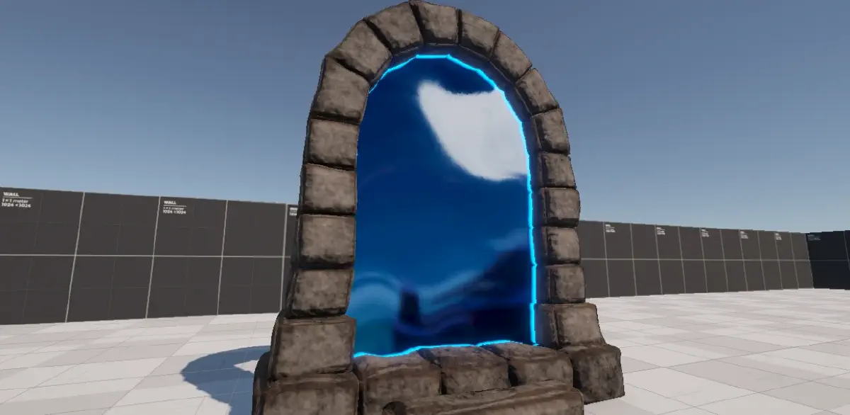
return float4(lerp(color.xyz, coloredDepth, depthDifference), 1.0);And just like that, the effect is complete! I hope you enjoyed this rather lengthy journey, but I think it has been worth it - the final effect looks really good, and with some extra particle effects we can re-create the full effect.
There are a few fixes we still need to account for, for example the distortion strength is applied the same no matter how far we are from the portal, which means at further distances the UVs are distorted so much we start seeing gaps.
Since this post is quite lengthy already, I will handle those in a separate post.
Thank you for taking your time to read this post, I very much appreciate your time! If you have any comments, suggestions, or requests, feel free to reach out to me via my social media below!
You can find the complete project, with both approaches, over at my shader vault on Github: