I vividly remember playing Dragon Age: Inquisition in 2021, where I stumbled upon a location called Emprise du Lion - a region defined by its cold climate, snow, and ice. One of the first things you encounter is a frozen lake that you need to cross to reach your next objective.
I remember being in awe about the ice, as it was nothing like I have seen before. The in-game shader used parallax to create a sense of depth, as if there was multiple layers of ice with cracks in-between. I knew I had to at least attempt to re-create this effect myself, so I began the research!
Parallax#
Initially I started looking into what is a parallax effect, it’s real life equivalent, and how it can be implemented using a shader.. only to be greeted by this Wikipedia quote:
Parallax is a displacement or difference in the apparent position of an object viewed along two different lines of sight and is measured by the angle or half-angle of inclination between those two lines.
If your initial thought after reading that quote was “what?”, don’t worry - I had the same reaction. On paper, the quote sounds scary but when we apply some visual examples we can quickly see what they mean.
Have you ever walked somewhere, and noticed that objects in the distance “move” slower compared to objects which are closer to you? For example, when I used to walk past a church, it was a couple of streets away from me, but the spire on its roof would move considerably slower compared to the building right in front of me. That’s is parallax!
Or perhaps you’ve played a 2D side scroller game, and you have noticed that elements further back from the camera moved slower compared to elements closer to the camera? This is quite common effect in 2D games, used to add depth to the background, and I have used it in a game jam project called “BaristaCats”.
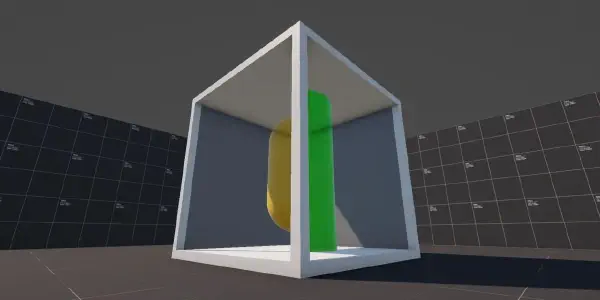
In the top part of the video I have used a orthographic camera (everything is flat 2D), whilst the bottom part of the video uses a perspective camera with the 2D elements actually spaced apart in world space - you can notice in the bottom part, various elements like the coffee machine, plant leaves, etc. don’t stay static, but actually move with the viewing angle.
Shader#
“That is a lot of theory, Dan - how about some code?” you might say, and I hear you, but I think it is quite important to understand parallax properly before starting to discuss the shader code as there will be a lot of difficult code that we will need to tackle, with some of it going over my head too.
Whilst doing some research, I have stumbled across Harry Alisavakis’ blog posts about parallax shaders (part 1 | part 2) - I highly recommend catching up on those, as Harry explains well the math and logic behind the parallax effect.
View Direction Tangent#
In order to create the depth effect we need the camera view direction tangent - we’ll be using the normal, tangent, and bitangent of the current vertex to calculate it.
Normal and tangent vectors are provided to us by Unity, and we can access them via the Attributes struct:
struct Attributes
{
    float4 positionOS : POSITION;

    float2 uv : TEXCOORD0;
    float2 uvCrackLayers : TEXCOORD1;

    float3 normalOS  : NORMAL;
    float4 tangentOS : TANGENT;
};
With those inputs, inside the vertex function, we can now calculate the view direction, the tangent sign and bitangent using the cross product operation.
struct Varyings
{
    float4 positionHCS : SV_POSITION;

    float2 uv : TEXCOORD0;
    float2 uvCrackLayers : TEXCOORD1;

    float3 viewDirTangent : TEXCOORD2;
};

Varyings vert(Attributes IN)
{
    Varyings OUT;

    OUT.positionHCS = TransformObjectToHClip(IN.positionOS.xyz);
    OUT.uv = TRANSFORM_TEX(IN.uv, _BaseMap);
    OUT.uvCrackLayers = TRANSFORM_TEX(IN.uvCrackLayers, _CrackLayers);

    float4 cameraPositionOS = mul(
        unity_WorldToObject,
        float4(_WorldSpaceCameraPos, 1.0)
    );

    float3 viewDirection =
        IN.positionOS.xyz - cameraPositionOS.xyz;

    float tangentSign =
        IN.tangentOS.w * unity_WorldTransformParams.w;

    float3 bitangent =
        cross(IN.normalOS.xyz, IN.tangentOS.xyz) * tangentSign;

    OUT.viewDirTangent = float3(
        dot(viewDirection, IN.tangentOS.xyz),
        dot(viewDirection, bitangent.xyz),
        dot(viewDirection, IN.normalOS.xyz)
    );

    return OUT;
}
Now, you might have noticed that we’re doing some multiplication of the .w parameter, let me explain.
Tangent space can be flipped when the object is mirrored, for that reason we can use unity_WorldTransformParams.w to see whether Unity has applied a handedness flip in the world transform - without this, our tangent space would be inconsistent and we’d get strange results.
Handedness is represented as a value between -1 and 1 (below zero is mirrored, zero and above is normal). Without applying this multiplication, the view direction tangent would be wrong compared to the world-space orientation of the object.
In case you are following using shader graph, you can achieve similar effect by connecting the following nodes - I have this part as a sub-graph, as we will be re-using those nodes for each layer (that is why I’m exporting each channel independently).
Thank you Binary Impact for the video tutorial on similar effect, as that has guided me in the right direction for re-creating this effect in shader graph.

Tiling and Offset node to create our texture UVs.
With our view direction tangent calculated, and with handedness correction applied, we can now start looking into setting up our textures and sampling them in the fragment function.
Texture Setup#
In the HLSL shader I will only be using a diffuse texture and a crack texture (packed texture), as I’m not yet as familiar with lighting setups in URP shaders. The shader graph version will be using a diffuse, normal, roughness, and a crack texture as the lighting calculations are handled for us.

Creating Layers#
You have made it this far, so I’m happy to say we’ve now reached the easier part of the post! Inside our fragment function we can now make use of the view direction tangent, but we need to normalize it first.
For UVs, we’ll add the normalized view direction to the crack-layer UVs.
float3 normalizedViewDir = normalize(IN.viewDirTangent);

float crackLayer = SAMPLE_TEXTURE2D(
    _CrackLayers,
    sampler_CrackLayers,
    IN.uvCrackLayers + normalizedViewDir
);
In the original example I have three layers, and we can use a for loop for this but GPUs aren’t always efficient with loops* especially with branching logic in them; we could unroll the loop and have the compiler write out the code for us, but I have another solution that is more elegant and in my opinion more readable and easier to maintain as each layer will have different strength.
*This isn’t strictly true, but its a good habit to get into when working with shaders. A simple loop might not hurt performance much, but the more logic we have in it, especially branching logic, we might notice performance dips.
float3 ratios = float3(1, 2, 3) * 0.25;
float3 offsets = _OffsetScale * float3(1, 2, 3);
float3 weight = offsets * ratios * (1.0 - ratios);
In the above snippet we are first calculating the ratios, in a for loop it would be i / cracksAmount, and we’re also calculating the offset values for each layer (layer 1 = 1x offset, layer 2 = 2x offset, etc.).
We can then multiply offsets by ratios in order to get the weights for each layer (notice that we’re using a float3 with each channel representing a layer).
Now we can simply declare a float3 variable, and assign the r/g/b (x/y/z) channels to the relevant channel in the texture, like so:
half4 frag(Varyings IN) : SV_Target
{
    float3 normalizedViewDir = normalize(IN.viewDirTangent);

    float3 ratios = float3(1, 2, 3) * 0.25;
    float3 offsets = _OffsetScale * float3(1, 2, 3);
    float3 weight = offsets * ratios * (1.0 - ratios);

    float3 cracks = float3(0, 0, 0);

    cracks.r = SAMPLE_TEXTURE2D(
        _CrackLayers,
        sampler_CrackLayers,
        IN.uvCrackLayers + normalizedViewDir * weight.r
    ).r;

    cracks.g = SAMPLE_TEXTURE2D(
        _CrackLayers,
        sampler_CrackLayers,
        IN.uvCrackLayers + normalizedViewDir * weight.g
    ).g;

    cracks.b = SAMPLE_TEXTURE2D(
        _CrackLayers,
        sampler_CrackLayers,
        IN.uvCrackLayers + normalizedViewDir * weight.b
    ).b;
}
We now have each layer of our cracks sampled, and stored in the float3. We can use dot operator to multiply each channel of cracks and cracks strength variable to have the “deeper” layers fade out slightly.
float parallax = dot(cracks, _CracksStrength.xyz) * 2;And lastly, we can sample our diffuse texture and linearly interpolate (lerp) between our parallax and the base texture.
I’m using the .r channel as interpolation value, since diffuse texture is black and white it provides a nice effect where the cracks are only visible in certain areas. We also want to multiply the result by the base color.
float parallax = dot(cracks, _CracksStrength.xyz) * 2;
half4 baseSample = SAMPLE_TEXTURE2D(
    _BaseMap,
    sampler_BaseMap,
    IN.uv
);

return lerp(parallax, baseSample, baseSample.r) * _BaseColor;
And of course, in shade graph we can achieve the same effect by connecting the following nodes together:

Please note that we are having to add each layer together, as if we just grabbed the result from texture sampling and passed it into the r/g/b channels (like in HLSL version), we’d get colored version of the cracks - adding makes sure they remain white.
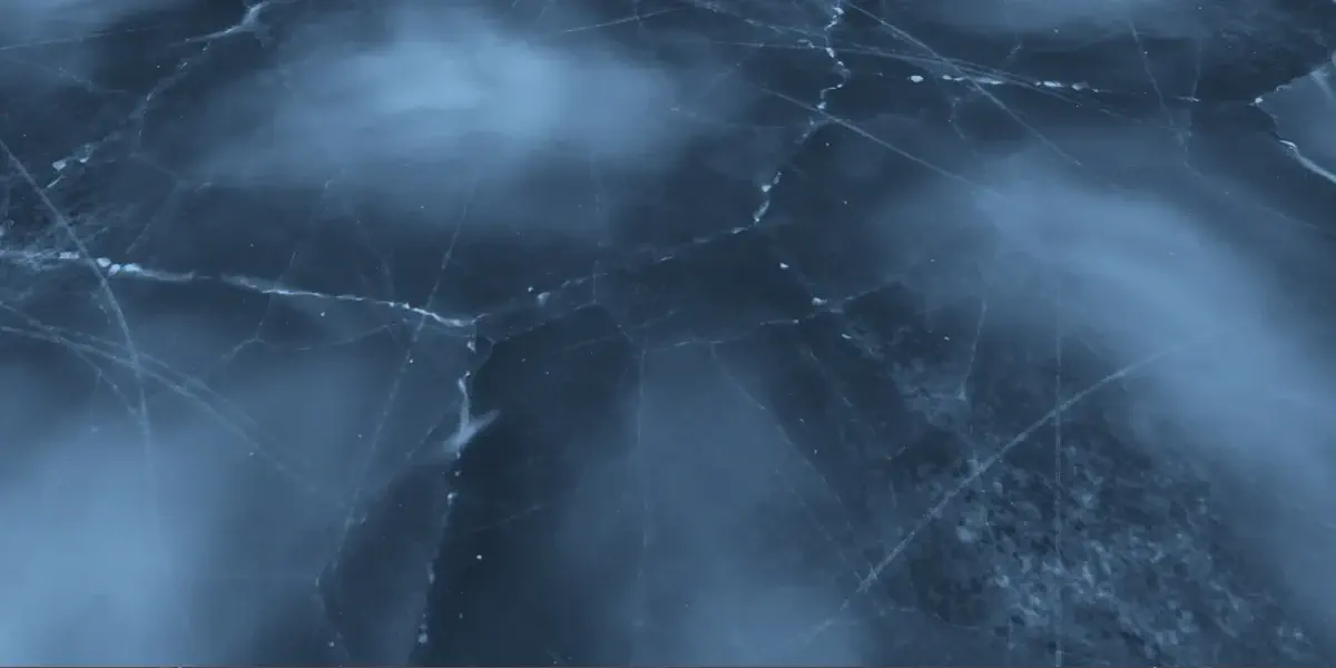
Final Result#
And with all of that, we should have the final result - cracked ice shader, which uses parallax effect to make it look like there is depth below the surface and more cracks have formed over time below the surface.

Thank you for taking your time to read this post, I very much appreciate your time! If you have any comments, suggestions, or requests, feel free to reach out to me via my social media below!
You can find the complete project, with both approaches, over at my shader vault on Github: